
Note: This manual may cover
several products or versions of one product.
Other products or versions covered by this manual may still be active.
Model 63-3/4 - RS-232 to RS-422 Converters
Reference Manual
| Table of Contents |
|
|
|
1.0 General Description 2.0 Specifications 3.0 Installation 4.0 Operation 5.0 Trouble Shooting 6.0 Connector Pin Assignments 7.0 Power 8.0 Help 9.0 Block Diagrams Warranty |
|
|
1.0 General Description
Product Description
Since the unit to be interfaced may look like a computer or a terminal, the
device required to couple different systems together requires the facility of
functioning as a DCE (Data Communications Equipment) or DTE (Data Terminal
Equipment). Because of this the converter is offered as a 63-3 or the 63-4. The
Model 63-3 is equipped with the RS-232 Interface that is designed to couple to a
modem. Therefore, the RS-422 port of the Model 63-3 will interface with a
terminal device which has a RS-422 interface. Similarly, the Model 63-4 is used
where RS-232 port is required to interface to the terminal.
1.1 RS-422 Description
The RS-422 specification as generated by the Electronic Industries Association
provides for a balanced voltage digital interface that is used for interchange
of serial binary signals between DTE and DCE equipment in any point to point
interconnection. The balanced voltage interface uses a differential driver and
receiver technique. Thus, two wire are required for each signal. The
specification provides for data signaling rates of up to 10 megabaud using
twisted pairs. Operation is allowed at 100,000 bits per second up to 1,200
meters and one megabaud per second up to 100 meters.
The design of the 63-3 and 63-4 is such that the use of a one-to-one
corresponding cable between a -3 and -4 on the RS-422 interface port will
provide a high speed Short Haul Modem link. Thus, data can be transmitted to a
100 KHz rate over distances of 4,000 feet. See Figure 1.
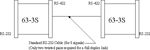
Figure 1
2.0 Specifications
2.1 Common
INTERFACE
Conforms to EIA RS-232 for RS-232 port and modified EIA RS-422 spec for the
RS-422 port. The following two tables describe in detail the input output
connections for each device.
In the case of the 422 connections, two pin numbers are designated separate by a
slash. The pin to the left of the slash is considered positive with respect to
the pin to the right of the slash.
Model 63-3
| RS-232 Port | RS-422 Port | |||
|---|---|---|---|---|
| Signal Name | Input / Output | Pin | Input / Output | Pin |
| TRANS DATA (TD) | OUT | 2 | IN | 4/3 |
| REC DATA (RD) | IN | 3 | OUT | 16/17 |
| REQ TO SEND (RTS) | OUT | 4 | IN | 5/6 |
| CLEAR TO SEND (CTS) | IN | 5 | OUT | 19/18 |
| DATA SET READY (DSR) | IN | 6 | OUT | 25/24 |
| SIGNAL GROUND (SG) | ||||
| DATA CAR DETECT (DCD) | IN | 8 | OUT | 11/12 |
| DATA TERM RDY (DTR) | OUT | 20 | IN | 9/10 |
| EXT TRANS CLOCK (TC) | OUT | 24 | IN | 8/7 |
Table 1
Model 63-4
| RS-232 Port | RS-422 Port | |||
|---|---|---|---|---|
| Signal Name | Input / Output | Pin | Input / Output | Pin |
| TRANS DATA (TD) | IN | 2 | OUT | 4/3 |
| REC DATA (RD) | OUT | 3 | IN | 16/17 |
| REQ TO SEND (RTS) | IN | 4 | OUT | 5/6 |
| CLEAR TO SEND (CTS) | OUT | 5 | IN | 19/18 |
| DATA SET READY (DSR) | OUT | 6 | IN | 25/24 |
| SIGNAL GROUND (SG) | ||||
| DATA CAR DETECT (DCD) | OUT | 8 | IN | 11/12 |
| DATA TERM RDY (DTR) | IN | 20 | OUT | 9/10 |
| EXT TRANS CLOCK (TC) | IN | 24 | OUT | 8/7 |
Table 2
Connectors: RS-232=25 pin male. RS-422=25 pin female; both connectors DB
type.
Data Rate: 256 KBPS
Transmission: Differential voltage in compliance with EIA RS-422.
Power: Self Powered - 110 volts AC, 50/60 HZ, 20 VA. Host Powered - +12
volts DC @ 125 ma., -12 volts DC @ 25 ma.
Size: 4"L X 2.2"w X 1"H, Plus wall mounted transformer for self powered
versions.
Environment: 0° to 50°C, 0% to 95% RH.
NOTE: On the Model 63-4 Pin 13 of the RS-422 connector is Signal Ground.
2.2 Power
The Model 63-3/4 Converters are available in both Host Powered and Self Powered
configurations. The Self Powered configuration, designated by an "S" after the
model number, is supplied with a wall mounted transformer which produces a low
voltage AC that is cabled to the device. Internally, this low voltage AC is
converted to +/- 12 volts and +5. The Host Powered version designated by an "H"
after the model number required that the user supply +12 and -12 volts on pins 9
and 10 respectively of the RS-232 connector. Internally, the +5 is then derived
from the +12 volts.
2.2.1
Host Powered: +12 volts DC @ 125 ma -12 volts @ 25 ma.
2.2.2
Self Powered: 110 volts AC, 50/60 HZ 20 VA.
3.0 Installation
3.1 Converters
The following two diagrams show the interconnection for the 63-3 and 63-4 when
used as converters.

Figure 2
3.2 Modem Operation
The following diagram shows the implementation of a Full Duplex Short Haul Modem
link utilizing a 6.3 and 63.4.
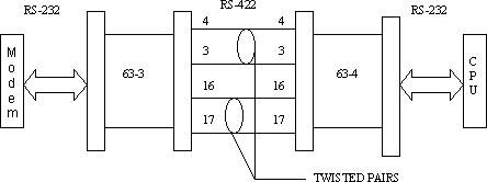
Figure 3
4.0 Operation
Each converter provides for signals in each direction. These signals are
processed simultaneously. It is not necessary to use all 8 signals. The unused
signals can be left floating.
5.0 Trouble Shooting
Individual converter verification can be accomplished by performing a loop back.
Typical loop back for a 63-4 connected to a CRT Terminal is shown in the
following figure. With a CRT operating in the full duplex mode any data entered
on the keyboard will not be displayed until it is received back at its input
port. If the converter is functioning properly, the data entered on the keyboard
will appear on the screen. This procedure can be used to test a portion of the
converter or the entire converter as shown.
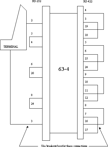
Figure 4
6.0 Connector Pin Assignments
Exact connector pin assignments have been shown in detail in the Specification
section of this manual.
7.0 Power
7.1 Host Powered
Power must be supplied to these units through pins 9 and 10 of the RS-232
connector. The voltage may be in the range of 11-13 volts positive on pin 9 and
in the range of 11-13 volts negative on pin 10. The absolute difference between
the + and - volts should not exceed ½ volt. The positive supply should be
capable of delivering 125 ma., whereas the negative supply must be capable of
delivering 25 ma.
The power inputs are diode protected to prevent damage from any inadvertent
application of improper polarity voltages on pins 9 and 10.
7.2 Self Powered
Operating power is generated on the combination of the wall mounted transformer
and regulation circuitry internally to the converter. The transformer plugs into
a 120 volt AC receptacle. A multi conductor 8 foot line cord delivers low
voltage AC to the converter. The internal rectifier circuits develop +/- 12
volts DC and +5 volts DC.
The transformer delivers 23 volts AC, is center-tapped and has a power
capability of 20 va. For applications using input voltages other than 120 vac.,
the user must supply his own transformer.
8.0 Help
Assistance can be obtained by visiting our
Technical Support
Center.
9.0 Block Diagrams
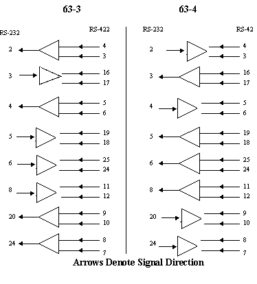
Block Diagrams 63-3 & 63-4
Warranty
Telebyte warrants the equipment to be free from defects in
material and workmanship, under normal and proper use and in its unmodified
condition, for 12 months, starting on the date it is delivered for use.
TELEBYTE's sole obligation under this warranty shall be to furnish parts and
labor for the repair or replacement of products found by TELEBYTE to be
defective in material or workmanship during the warranty period. Warranty
repairs will be performed at the point of manufacture. Equipment approved for
return for warranty service shall be returned F.O.B. TELEBYTE factory and will
be redelivered by TELEBYTE freight prepaid, except for non- continental U.S.A.
locations. These deliveries will be sent COD freight and import/export charges.
THE ABOVE WARRANTY IS IN LIEU OF ALL OTHER WARRANTIES, EXPRESSED OR
IMPLIED, STATUTORY OR OTHERWISE, INCLUDING ANY IMPLIED WARRANTY OF
MERCHANTABILITY OR FITNESS FOR A PARTICULAR PURPOSE. TELEBYTE SHALL NOT BE
LIABLE FOR ANY DAMAGES SUSTAINED BY RESELLER OR ANY OTHER PARTY ARISING FROM OR
RELATING TO ANY EQUIPMENT FAILURE, INCLUDING, BUT NOT LIMITED TO CONSEQUENTIAL
DAMAGES NOR SHALL TELEBYTE HAVE ANY LIABILITY FOR DELAYS IN REPLACEMENT OR
REPAIR OF EQUIPMENT.
Out of warranty equipment may be returned to the Greenlawn, NY customer service
facility prepaid as described above. Return shipping charges will be billed to
the customer. The repaired unit will have a 90 day warranty. In those cases
where "NO TROUBLE" is found, a reduced charge will be billed to cover handling,
testing and packaging.
Whether in or out of warranty a Return Material Authorization number (RMA) is
necessary. Assistance can be obtained by visiting our
Technical Support
Center.
Document No. 0315-0026/Rev. B