![]()
Model 66/266/366RS-232 To RS-485
|
1.0 General DescriptionThe Telebyte Model 66/266/366 converter provides a convenient method of interfacing EIA-232-based equipment with an RS-485 network using a half-duplex, single twisted-pair transmission protocol. The Model 66/266/366 provides the capability for a high-speed, low cost, local area network. Up to 32 users can be supported at rates up to 38.4K Baud and total separations of 6,000 feet. The Model 366 has the patent-pending DataSpy™ feature for installation and troubleshooting. Note: While the Models 66 and 266 are no longer available, they are still supported. 1.1 DataSpy™ Feature (Model 366 only)Your new Telebyte product incorporates the patent-pending DataSpy™ feature, an LCD display designed to provide meaningful information to the user. It will assist in the initial installation and check out; thereafter it can be used as a performance monitor. In the case of a system problem, it provides information as to the status of the local link. The Telebyte logo shown on the LCD display indicates the unit is powered. For power-stealing devices such as a converter, it is an indication that sufficient power is being applied to operate the device. The LCD display uses less than 1 milliWatt of power.
|
|
|
|
The data display on the LCD consists of graphical representations of TD (Transmit Data) and RD (Receive Data). Each of these signals is displayed the way a bit-change waveform would appear on an oscilloscope. Ordinarily, TD and RD are low or a minus voltage in the quiescent state. When data is transmitted, the transmit signal is brought high to a positive voltage. These two signal states are displayed on the LCD by either a low segment or a high segment. The low segment represents the minus voltage (the mark condition) while the upper segment represents a positive voltage (the space condition). The vertical bar connecting the lower segment to the upper segment is always on when power is applied. If the transmit signal is in the quiescent state (continuously low) only the lower segments and the vertical bar will be illuminated. This indicates a constant negative state. If the transmit or receive inputs to the device were streaming, i.e., in the positive mode continuously, the LCD display would show the vertical segment and the upper segments only. For those cases where there is valid data transmission, both the upper and lower segments will be displayed simultaneously. A variation in display intensity between lower and upper segments will give the user a perception of the amount of data being transmitted. The LCD display also
shows the status of the following control signals: CTS, RTS, DSR, DCD,
and DTR. These signals are displayed as mnemonic symbols, composed of
three letters each, on the bottom line of the display. The presence of
the three-letter mnemonic indicates that the respective control signal
is high or positive. If the control signal is negative, the three-letter
mnemonic is not displayed. For most full-duplex data-only converters,
CTS and RTS are connected together while DSR, DCD, and DTR are connected
together. The DataSpy™ LCD display will help verify correct operation. 2.0 Specifications2.1 InterfaceConforms to EIA RS-232 and RS-485 specifications. 2.2 Connectors2.2.1 Model 66 RS-232: DB25M. 2.2.2 Model 266 RS-232: DB25F. 2.2.3 Model 366 RS-232: DB25M or F (as ordered). 2.2.4 Model 66/266 RS-485: four-position terminal block. 2.2.5 Model 366: five-position terminal block. 2.3 Data Rate0 to 38.4 KBPS |
2.4 SwitchesDTE/DCE selector switch:
allows reversing of Pins 2 and 3 of EIA-232 connector. |
|
|
|
2.5 IndicatorsModel 66/266: three red LED's indicating TD, RD, and RTS/CTS. Model 366: equipped with an LCD display for data, five control signals and power. 2.6 Power115VAC @ 60 Hz (220 VAC @ 50 Hz optional). 2.7 SizeModel 66/266: 4" L x 2.2" W x 1" H (102mm x 56mm x 25mm) Model 366 : 2" W x 4.15" L x 0.79" H (50.8mm x 105.4mm x 20.1mm) 2.8 Environment0o to 50o
C, 5% to 95% relative humidity. 3.0 InstallationThe Model 66/266/366 is designed to interface EIA-232 with RS-485 equipment. The EIA-232 device can be either a DTE or DCE type device. The DTE/DCE selector switch allows for reversing Pins 2 and 3 ( TD and RD), thereby eliminating the need for null modem cables. If the switch is in the DTE position, Pin 2 of the RS-232 connector is an input for the Model 66 and 266 and an output for the Model 366. The half-duplex nature of RS-485 allows for a Master-Slave configuration. In a network, the master will poll the slaves through the single twisted pair and request that only one device access the line at a time. |
|
|
||||||||
|
||||||||
|
Two pairs of screw terminals are provided to allow the pass through of the twisted pair. This simplifies installation of a network. There are internal connections between both positive and both negative terminals. The Model 66/266/366 can
be interfaced to the network bus in two configurations. However, the
results of both configurations are identical. The first configuration
allows for a direct splice into the bus. The second configuration
creates a "T" at the bus and runs a stub of wire to the unit. 4.0 OperationOperation in an RS-485 environment requires all devices attached to the network to have some level of intelligence in order to establish an orderly flow of data on the single twisted pair. The Model 66/266/366 offers three possibilities for hardware data flow control. The user selects the mode which avoids the contention problem. Unless contention is resolved, there is the possible collision of data caused by two devices attempting to transmit simultaneously. The software control is the responsibility of the user. On all Models the RTS (Pin 4) and CTS (Pin 5) signals of the EIA-232 connector are jumpered together. This combined signal (referred to as RTS) is used to control the transmitter and, depending on the mode, can also control the receiver. The Model 66/266/366 can only transmit data on the RS-485 port if RTS is asserted. Note: On the Model 366 only: if the RTS
signal cannot be controlled, then carefully open the covers and locate
JP1 and move the jumper to the adjacent pin. This allows the TD signal
to control the transmitter. |
|
Positions 3 and 4 of the
dipswitch control the I/O circuits of the RS-485 port as indicated
below: |
|||||||||||||||||||||||||
|
|||||||||||||||||||||||||
|
An analysis of the operating modes reveals that Mode 2 or 3 are the most useful in the majority of installations. Mode 3 allows the converter to "listen" to the line at all times, including its own transmission. This allows observation of data collisions if they occur. The RTS indicator displays the status of the RTS/CTS signal applied to the control ports of the RS-485 transmitter and receiver as set by the Mode switches. Mode 4 disables the transmitter completely, regardless of the RTS/CTS signal; the RTS display reflects the disabled status.
4.1 Termination of the LineThere are four
user-selectable resistive terminating values which are implemented using
switches A and B of the dipswitch. As the length of the transmission
cable and the number of users increases, the chosen value becomes more
critical to error-free operation. Typically, devices at the end of a
long bus are terminated and units multi-dropped between the ends are not
terminated. The cable used to connect devices off the long bus should be
kept as short as possible. The value chosen should match the
characteristic impedance of the twisted pair being used. The termination
value can be selected using the following table: |
|||||||||||||||||||||||||
|
|||||||||||||||||||||||||
5.0 TroubleshootingThe following is a list of possible problems that may arise during the installation and solutions to those problems: 1. The data being received is garbled. a) The DTE/DCE switch is not set properly (see Section 3.0, "Installation"). On the Model 366, observe the LCD and verify that TD and RD are shown as low in the quiescent state (see Section 1.1, "DataSpy™ Feature"). b) The equipment that the Model 66/266/366 is connected to does not have the communication parameters set the same. c) "+" and "-" are reversed. On the Model 66 and 266 look at the RD LED, if it is ON continuously then the leads are reversed. On the Model 366 look at the LCD and if RD is shown as a constant high or streaming (see Section 1.1, DataSpy™ Feature") then the wires are reversed. d) One of the two wires is broken. 2. No data is being received. a) Customer equipment not connected to the Model 66/266/366. b) The DTE/DCE switches are not set properly (see Section 3.0, "Installation"). c) One or more wires between the modems are open. d) Link connection exceeds maximum specified distance. Individual converter performance can be verified if the device to which the converter is connected is capable of full-duplex operation. A standard CRT terminal is ideal for this test. In this mode the terminal will generate data from its keyboard and be transmitted via Pin 2. However, data will not be displayed until it is received at its input port, Pin 3. The converter may now be
tested by setting the following switches: |
|
|||||||||||||||||||||||||||||||||||||||||||||
|
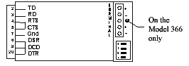
6.0 RS-232 Pin Number Assignments |
|||||||||||||||||||||||||||||||||||||||||||||
|
|
|||||||||||||||||||||||||||||||||||||||||||||
|
* These signals can be
reversed using the selector switch. 7.0 PowerThe Model 66/266/366 can
be either host or self powered. In the self-powered mode, a wall-mounted
transformer supplies low voltage AC and the required +12, -12, and +5
Volts are generated internally. For host-powered operation (Models 66
and 266), +12 and -12 Volts must be supplied on Pins 9 and 10 of the
EIA-232 interface. For Model 366, supply +12 volts on Pin 9. |
|||||||||||||||||||||||||||||||||||||||||||||
7.1 Model 66The Model 66 is powered by a small, wall-mounted transformer that supplies 9 VAC. The transformer is connected to the Model 66 through the captive line cord. One of the low-voltage wires from the transformer is Signal Ground and is appropriately marked. 7.1 Model 266The Model 266 is powered by a small, wall-mounted transformer that supplies 9 VAC @ 500 mA. The transformer must be connected to the Model 266 through the 3.5mm connector located on the side of the unit before plugging the transformer into the wall. 7.2 Model 366The Model 366 is powered
by a small, wall-mounted transformer that supplies 12 VDC @ 500 mA. The
transformer must be connected to the Model 366 through the 1.3mm
connector located on the side of the unit before plugging the
transformer into the wall. 8.0 HelpAssistance can be obtained by visiting our Technical Support Center.
WarrantyTELEBYTE warrants the equipment to be free from defects in material and workmanship, under normal and proper use and in its unmodified condition, for 12 months, starting on the date it is delivered for use. TELEBYTE's sole obligation under this warranty shall be to furnish parts and labor for the repair or replacement of products found by TELEBYTE to be defective in material or workmanship during the warranty period. Warranty repairs will be performed at the point of manufacture. Equipment approved for return for warranty service shall be returned F.O.B. TELEBYTE factory and will be redelivered by TELEBYTE freight prepaid, except for non-continental U.S.A. locations. Non-continental deliveries will be sent COD freight plus import/export charges. The above warranty is in lieu of all other warranties, expressed or implied, statutory or otherwise, including any implied warranty of merchantability or fitness for a particular purpose. TELEBYTE shall not be liable for any damages sustained by reseller or any other party arising from or relating to any equipment failure, including, but not limited to consequential damages nor shall TELEBYTE have any liability for delays in replacement or repair of equipment. Out of warranty equipment may be returned to the Greenlawn, NY customer service facility prepaid as described above. Return shipping charges will be billed to the customer. The repaired unit will have a 90-day warranty. In those cases where "NO TROUBLE" is found, a reduced charge will be billed to cover handling, testing and packaging. Whether in or out of warranty, a Return Material Authorization (RMA) number is necessary.Assistance can be obtained by visiting our Technical Support Center.
|